Extrusion Die Design: From Theory to Practice
2024.06.28For production lines of sheets, films, and coatings, the critical function of extrusion dies is to ensure that the plastic can be uniformly extended and formed after entering the die chamber. However, the physical properties of each type of plastic vary, and the entire process is easily affected by external factors such as temperature and pressure, which can lead to instability in plastic flow within the die chamber or changes in viscosity causing uneven flow rates. Therefore, to ensure that the plastic remains in a stable state within the chamber, producing the desired uniform thickness and width, and to ensure the continuous and smooth operation of the entire extrusion line, an appropriate die design is crucial.
The Magic of Mold Flow simulation: Breakthrough Advances in Extrusion Die Design
In addition to extensive experience, die design can be further optimized through simulation analysis to refine the geometric design details of the die. This optimization can prevent issues such as uneven thickness caused by inconsistent material flow, sharkskin phenomena caused by uneven flow rates, and cost wastage. Whether dealing with a single layer or multi layers structure, simulation analysis can assist die designers in identifying the most suitable die design. Furthermore, modifications to die design and formulation changes can utilize simulation analysis as a tool, aiding in process improvement and product development.

The function of dies in extrusion lines is to shape plastic into uniform thickness and achieve the expected width.
How to define the most suitable die design? Fundamentally, the basic components of a die include the die body design, thickness adjustment, and width adjustment design (if necessary). The design of thickness and width adjustment is based on product dimensions. However, the most critical aspect is the design of the internal flow channels. Each die manufacturer has different designs, processing experiences, and definitions, but essentially, they must meet three criteria:
1.Outlet uniformity must be less than <3%.
2.Minimal pressure loss is preferable.
3.Shear stress depends on material rheology, die temperature, and feed rate, with more uniform retention time through the die being better.
The interior of the die is primarily divided into several zones: the feed inlet, main channel, relaxation zone, and die lips. Plastic enters the chamber through the feed inlet and is evenly distributed across the entire width via the design of the main channel. The main channel can have configurations such as T-shape, fish-tail shape, or hanger shape depending on the properties of the plastic. The relaxation zone allows the plastic to release stress over time. After the landing area, the plastic exits through the die lips in a uniform thickness state. Subsequent mechanisms in the die aid in cooling and setting the plastic into its final shape.

The extrusion die channels can be into hanger type (left), T-shaped (middle), and fish-tail type (right) , depends on different polymer properties.
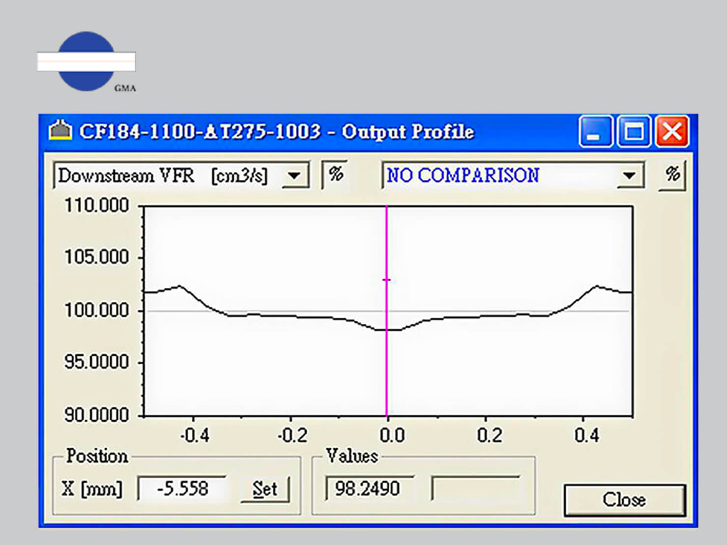
Lip gap and product thickness are closely related. The design of the gap adjustment is based on adjusting the turning force of screws and the flexible die lip . To ensure that different gaps achieve uniform thickness, plastic enters the chamber through a certain pressure to the die lip outlet. Therefore, in simulation, special attention is paid to ensuring that under different flow rates and die lip openings, the outlet uniformity is less than 3%.

With the same output, different lip gap, we can see different uniformity from simulation.
Learn more: Three Key Techniques for Adjusting Lip Opening in Extrusion Dies
Pressure is a crucial factor affecting extrusion lines. To ensure smooth shaping, the die must maintain stability, with minimal pressure drop from feed to exit being ideal. Excessive pressure can cause die deformation, while insufficient back pressure may hinder plastic movement or lead to significant flow rate disparities. The pressure within the die chamber determines both the die body thickness and structural integrity.

With the same lip gap but varying output, from simulation, we can see different levels of uniformity and pressure variations will occur. It's important to note the changes in pressure drop (loss) from the inlet (red) to the outlet (blue).
Shear stress and residence time: Proper flow velocity of plastic within the die chamber can prevent the formation of stagnant layers. When plastic flow velocity is too low, residence time increases. Low flow velocity near the die walls can not only lead to plastic degradation but also cause significant differences in velocity compared to the central layer. When shear stress reaches a critical value, sharkskin phenomena may occur. Typically, adjusting temperature and adjusting lip gap are used to mitigate this issue. The minimum shear rate for dies is generally around 10 (1/s).
Design and Technological Challenges in Co-extrusion
For co-extrusion, such as in the production of multi-layer films used in food packaging and medical applications, two methods are commonly employed: using feed blocks and dies to create multi-layer structures, or employing multi manifold dies. The choice between these methods depends on the plastic's properties, which dictate the preferred manufacturing approach. Regardless of whether using feed block or multi manifold dies, the design of the flow channels is optimized based on the principles mentioned above through simulation and geometric calculations.
In multi-layer structures, uneven thickness or incorrect ratio of each layer are most likely to occur, especially when there are significant viscosity differences between layers. When using multi manifold dies to process plastics with large viscosity disparities, especially in cases where the viscosity of the outer layers differs significantly from that of the inner layers (e.g., low viscosity on the outer layers and high viscosity in the middle), careful attention is needed in designing the flow channel compression from the feed inlet to the outlet. This design consideration aims not only to avoid uneven thickness or ratios but also to prevent issues such as edge encapsulation at the ends of the layers.
Therefore, multi manifold dies often incorporate separate temperature control systems for each layer. This allows for precise temperature adjustments to maintain viscosity within controlled ranges for each layer, thereby optimizing the processing of materials with varying viscosities.
 Apply multi manifold dies for processing multiple plastics
with significant viscosity differences, independent temperature control for
each layer makes a substantial contribution to achieving uniform thickness in
practical applications.
Learn more: Innovation in Co-Extrusion Process: Multi Manifold Die
The feed block is used for handling multilayer structures of plastics with similar viscosities. In its design, special attention needs to be paid to the stress differences among various plastics, which can lead to incorrect ratios. The feed block is equipped with adjustment device, primarily to control the interfaces between layers, thereby achieving expected ratios.
 The feed block is used for handling multilayer
structures of plastics with similar viscosities, adjusting layer interfaces through
its adjustment device.
Learn more: Unlocking the Three Secrets of Co-Extrusion Feed block
More and more people realize the importance of extrusion die in various extrusion production lines, the advancement in simulation analysis technology enables more refined and scientific die designs, significantly reducing abnormal production conditions in extrusion. The synergy between simulation analysis, design experience, and processing expertise forms an indispensable golden triangle for producing high-quality extrusion dies. Future die designs will advance towards even greater precision, promising further enhancements for more possibilities of extrusion production lines.


