Three Key Techniques for Adjusting Lip Opening in Extrusion Dies
2024.01.31The design of extrusion dies is primarily divided into three main parts: the feed inlet, the channel, and the lip opening design. The lip gap design includes corresponding lip gap adjustment device. For extrusion die operators, adjusting the lip opening is one of the most frequently used device. What are the different types of lip design, and how should one choose and use them? Let's quickly uncover the secrets of lip gap adjustments.
What is Lip gap?
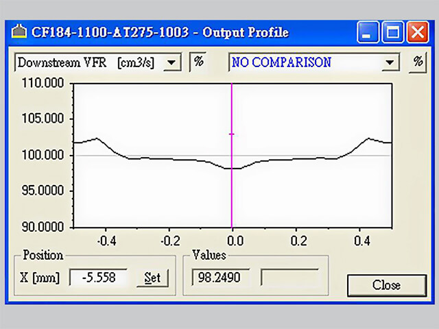
Lip gap refers to the spacing at the discharge location when the two steel of die bodies are combined. The gap of the lip depends mainly on the thickness of the product. Inappropriate lip gap will affect the pressure distribution inside the die chamber. Therefore, lip gap design typically utilizes simulation flow software for assistance. The adjustment methods for lip gap configuration vary based on the thickness adjustment range. Common lip gap adjustment methods include adjusting screws (manual and automatic), rapid gap adjustment , and interchangeable lips.

Lip
gap refers to the spacing at the discharge location when the two steel of die
bodies are combined.
Secret
Technique 1: Adjusting Screws
The
most common method for adjusting lip gap is through "adjusting
screws." By leveraging the elasticity of the mold steel and the convenient
application of force through screws, the lip gap can be altered. Two common
forms are "push only" and "push and pull" (also known as
differential screws).
Push-only,
as the name suggests, involves turning the screw downward (compression), narrow
the lip gap. Returning the screw to its original position allows the mold
steel's inherent elasticity to restore the lip gap. Push & pull screws, on
the other hand, can also narrow the lip gap by turning the screw downward,
applying pressure. The difference lies in this type of screw's ability to
stretch the mold steel's elasticity by pulling the screw upward within a
limited range, thereby expanding the lip gap. Based on user experience, films
with thin product thickness typically have a small adjustment range and
commonly use push-only screws. For sheet (thickness above 0.5mm), push &
pull screws are often preferred as they are easier to adjust.

Left:
Push-only lip adjustment screws, Right: Push & pull lip adjustment screws
In
addition to the manual adjustment mentioned above, the adjustment of lip screws
also includes an automatic adjustment mode. The adjustment principle of
automatic bolts is the same as that of manual adjustment screws. The only
difference lies in the fact that when the production line is running, manual
adjustment screws require the operator to use tools to apply force to the screw
for adjustment. In contrast, automatic bolts rely on mechanically-driven
adjustments received through signals.

Left:
Extrusion die equipped with automatic control bolts.
Right:
The internal structure of automatic bolts includes electric heating elements,
ensuring a stable temperature that enables the bolts to operate.
The
configuration of adjusting screws in lamination dies is significantly different
from other types of dies. One type of curtain lamination die, often applied in laminating
paper and thin film substrates, features a four-piece structure where the die
body and lip are separate. This stands in stark contrast to the majority of die
where the body and lip are a single integrated structure. The separation of the
lip from the body is a distinctive characteristic. Because of this separation,
when there is a need to make significant adjustments to the lip gap ,especially
in cases where the lip gap in curtain lamination die is fixed, applying even
force through screws on both sides of the lip ensures uniformity in lip gap
adjustments.

The
configuration of adjusting screws in lamination dies is significantly different
from other types of dies.
Secret
Technique 2: Quick lip gap adjustment
The
typical range of lip gap adjustment with screws is generally within 1mm.
However, for products requiring larger adjustment ranges, a quick lip gap
adjustment system can be the optimal choice. Through a linkage design, the lip gap
can be rapidly expanded without the need to individually adjust each screw, as
in the case of the aforementioned screw adjustment. Using this system, you only
need to rotate the sleeve on the side to drive the
linkage to achieve the desired adjustment. Quick lip gap adjustment can
typically accommodate thickness adjustment ranges within +/-2mm.

Rotating
the sleeve on the side to drive the linkage to achieve the desired adjustment.
Secret
Technique 3: Interchangeable Lips
For foam products and thick sheets (product thickness above 3mm) with greater thickness adjustment requirements, "interchangeable lips" can be employed. In this design, one side of the lip is not integrated with the die body. When dealing with varying thicknesses, the lip can be replaced to increase the lip gap. Typically, a set of extrusion die may be equipped with two to three sets of interchangeable lips. The adjustment range with interchangeable lips can reach up to 5mm. However, due to the connection between the interchangeable lips and the body, there may be minimal gaps over time due to thermal expansion and contraction effects. This could potentially impact certain plastics (such as PC/PET), so it is not recommended for use in such cases.

Interchangeable
lip is applied for foam products and thick sheets.
More
Tips: Lip Heater and Restrict Bar
In
response to the characteristics of plastics and product requirements, the
heaters are often installed in the lip to prolong the cooling time of plastics
from the inlet to the outlet. Unlike heaters inside the die body used to heat
the die itself, lip heaters are primarily employed to maintain the temperature
of the lip, ensuring a more stable forming process for plastics after passing
through the lip.
Another
excellent companion for adjusting lip gap is restrict bar. For high production output
or materials with a higher proportion of recycled content, as well as special
formulations, a restrict bar is installed on the die body. When the operator
has used screw adjustments to control product thickness but still cannot
achieve an acceptable and stable production state, the restrict bar can be
utilized to adjust the flow path inside the die channel, altering the plastic
flow rate to achieve a uniform discharge state.

Restrict
bar can be utilized to adjust the flow path inside the die channel, altering
the plastic flow rate to achieve a uniform discharge state.
With advancements in modern extrusion die design and manufacturing, adjusting lip gap has become more intuitive and user-friendly. The assistance of simulation flow software and process optimization allows operators to have more precise control over the adjustment process, reducing the risk of lip damage or deformation caused by improper adjustments. This also means that, during the die delivery stage, the initial calibration of lip gap has become more refined, providing users with a more convenient and secure operating environment. Consequently, the application of these technologies not only enhances production efficiency but also delivers higher-quality finished products.


